
Welcome to our journey into the world of smart doorbell security. In this article, we will take you through our thought process as we dive into assessing the security posture of a smart doorbell IoT device. We will explore various approaches and methodologies we considered and used along the way, highlighting both the things that failed and the things that worked. The aim of this article is to show how such an assessment could be approached and provide you with enough insights and takeaways to enable you to take on your own IoT security research projects.
Project background
All things IoT are already commonplace in everyday life; they have been around for a few years and are becoming more popular, with their numbers increasing substantially each year. A quick online search lists many articles that suggest there are already over twice as many IoT devices as there are people on the planet [1], [2] which realistically means many households have at least a few of these on average.
IoT devices perform various roles: from providing convenience such as smart lighting or heating [3], through data logging and analytics in industrial settings [4], to security and many more, sometimes packing several of those roles into one device.
For many years IoT devices were designed with usability in mind over security [8], which has led to several security breaches in the past [5] and still to this day. Even though IoT security is slowly improving, big breaches happen [6], [7].
Taking all this into account, my colleague and I decided to take a look at an IoT device and see just how secure it is, settling on Smart Doorbells.
At a high level, we have split the research into the following phases. However, this article focuses mainly on Phases 1-3:
- Phase 0: Test Environment Setup
- Setting up Wi-Fi network for testing.
- Setting up virtual machines and tooling.
- Setting up an Android emulator or obtaining a rooted physical device for the doorbell app.
- Phase 1: Initial Background Research
- Gathering information on previous research, vulnerabilities, publications, device documentation, etc.
- Phase 2: Obtaining Interactive Access
- Debug capabilities (network or physical interfaces), firmware acquisition (dump, download from the vendor, intercept the update process).
- Escalate privileges for unrestricted access.
- Phase 3: Attack Surface Mapping
- Network services, processes, points of data entry, etc.
- Phase 4: Vulnerability Research
- Code review, reverse engineering, fuzzing, etc.
- Tooling development.
- Phase 5: Exploit Development
- Selection of potential vulnerabilities for exploiting.
- Creation of proof of concept.
Target selection
Smart Doorbells provide security and convenience, typically being equipped with a camera, motion detection, a microphone for 2-way intercom, ability to store video footage locally or in the cloud, and the ability to be controlled remotely by the user. Remote control is typically provided via a mobile application, which allows the user to view live or recorded video feeds, get notifications on doorbell rings, and speak to the person at the door via their mobile phone. Internet connectivity for these devices is generally provided via a home internet connection, usually by connecting to the Wi-Fi network.
There are many different IoT Smart Doorbells available, some from well-known companies such as Amazon (e.g. the Ring Video Doorbell) and some by little known vendors, many of which being Chinese companies. In both cases, there were security issues with these devices in the past [13], with the well-known companies usually fixing them pretty quickly [9]. Instead of focusing on something that has been security researched plenty of times previously, we decided to target a lesser-known brand, which did not appear to have been researched previously. To find that target, we have come up with the following selection criteria:
- The device is available to buy on Amazon, as it is an accessible platform for many people all over the world.
- A device price up to £100, as a reasonable budget option.
- The device is popular and frequently bought, as indicated by ratings on Amazon item listings.
- The device comes from a lesser-known vendor.
With these in mind, we have ended up selecting the XTU brand, specifically the J7 model. Why pick a brand that’s not really been on the radar before? It is possible there are more interesting vulnerabilities to find.

Figure 1: XTU Smart Doorbell Listing on Amazon, showing 1000+ devices were bought in the past month
Target recon and background research
With our test environment ready (i.e. VMs, test Wi-Fi network and a rooted Android mobile device for testing), and the device in the mail, it was time to do some background research before our target arrived (we did some searching prior to ordering, but did not find any previous security research on the XTU doorbell cameras). The goal of this phase was to gather as much information about the target as possible from publicly available sources, before we began considering how such a target can be attacked.
The first and simplest thing to do would be to find the device user manual, which was relatively easy with some quick search engine queries. Funnily enough, the manual for this model was not actually available on the vendor’s website. However, we found the manual for what looked like the same doorbell but sold under a different brand. In total we found seven brands that sold the same device, and it’s likely there were more if we searched further.

Figure 2: The J7 doorbell camera model was sold under several different brands
Just from the Amazon listing and the user manual, we have already gathered a lot of useful information that we used for our threat modelling later. We now know the following:
- The device connects to the internet through Wi-Fi (2.4 GHz only).
- There is a mobile app component used as an interface for the user to manage and operate the device.
- There is an external wireless chime that can be used with the doorbell device.
- The device can store data (video recordings) on a local SD card or in the cloud (subscription based).
- The device bracket is mounted on a wall with screws, and the device itself is secured to the bracket with a “security screw”.
All this information along with the mobile app name helps to determine the device capabilities and potential attack paths.
Going a step further, we wanted to obtain low level device hardware information. This could include things like schematics, datasheets, internal pictures of the device hardware, part numbers, etc. All that information is valuable to attackers and researchers alike, because it helps to determine potential avenues of obtaining control over the device via debug or other interfaces which are usually not mentioned in end-user manuals.
Excellent sources of such information are usually websites that contain the FCC database information. Every device that is capable of transmitting data over radio waves (e.g. Wi-Fi, Bluetooth, etc.) and therefore has the potential to cause interference must be first approved by the FCC before it can be sold in USA. Once a device is approved by the FCC it is assigned an FCC ID, which can be used to look for information on the device. Part of the application process involves a teardown of the device and taking close-up photographs of external and internal components, which are later published and available for anyone to review. Normally the FCC ID would be found somewhere on the device packaging, however, we were still waiting for ours to arrive. In the meantime, we have managed to find an FCC ID in a user manual of the same looking device sold under a different brand, which was a good starting point. We have reviewed the FCC information, however, it looked like the ID was for a different model [10] (J6 instead of J7), so we decided to wait for the device to get the correct ID while doing other research in the meantime. Funnily enough, when the device arrived the FCC ID on the packaging was the same. Later, we determined the hardware was quite similar between the J6 and J7 models, with small differences in the form factor and specific components used, which suggests it was just another revision of essentially the same hardware.
At this point it was quite blurry as to who the actual device manufacturer is, with the same model being sold under several different brands, by companies all based somewhere in China within the Shenzhen city (some even in the same building). It certainly looks like XTU CAM is not the actual manufacturer of the device, with the same going for other brands we have found while researching the device online. This is a common scheme: resellers bulk buying generic devices from large manufacturers and selling them on under their own brand. It begs some questions though; for example, how do all these resellers handle releasing security updates? Do they come from the original equipment manufacturer? Who do you inform when you find a security bug in a device? These sorts of questions are relevant to both organisations and individuals who choose to use an IoT device in their places of business or homes, but the answers are not always clear in these cases.

Figure 3: Useful information about the device is publicly available when searching for the FCC ID
A quick review of the internal photos tells us a few things that could be useful later:
- The device has 2 interfaces which could potentially be used for debugging/interactive access (a 6-pin interface and a 4-pin interface – possibly UART [11]).
- There is one main Micro Controller Unit (MCU), which is what controls the device operations (like a CPU in a regular computer).
- There is one Integrated Circuit (IC) which is most likely responsible for Wi-Fi and Bluetooth communications.
- There is a flash memory chip, which likely contains the device firmware.
At this point we didn’t yet start cataloguing the component parts and numbers, since our hardware would most likely have similar but not necessarily the exact same parts as shown on the internal photos. With all this information, including some previous academic research on general IoT device security, we moved onto doing some simple threat modelling.
Threat modelling and establishing potential attack paths
Threat and risk modelling can be a complex and time-consuming process, so we have deliberately simplified our approach in this project and produced a high-level threat model to get to the technical review quicker. However, given a larger timescale the most suitable approach to evaluating security posture of an IoT device would be to utilise the Open Worldwide Application Security Project IoT Security Testing Guide (OWASP ISTG) [12].
Considering all we knew so far without touching the physical device, we produced the following basic threat model:
Asset
A smart doorbell device with a camera that can monitor surroundings, record videos and sound, take photos and send alerts or notifications to users’ mobile phones. The device has a mobile app component which can be used to control the device in various ways. Internet connectivity is provided for the device by connecting it to a Wi-Fi network.
Adversary Model
A skilled attacker with resources normally available to an individual or an organised criminal group without nation state backing. The research would be based on assuming a position of such an attacker or attackers who are looking to exploit the target and compromise the data and device to use for financial gain, e.g. by blackmail, extortion, creating a botnet, etc.
Potential Threats
- Data theft from the device.
- Data theft from the cloud storage.
- Information disclosure over the network.
- Denial of Service.
- Spoofing video/photo feeds.
- Device takeover (e.g. remotely gaining control over it).
Potential Attack Surface
- Physical:
- Debug interfaces (interactive access).
- Data storage (flash memory, RAM, local storage such as an SD card).
- Application (mobile app):
- Could include typical attack vectors for a mobile app, e.g. authorisation/authentication weaknesses, information disclosure, etc.
- Network:
- Debug interfaces (interactive access).
- Interception and/or spoofing of traffic.
- Cloud services:
- Could include typical attack vectors for a web app or API, e.g. authorisation/authentication weaknesses, information disclosure, etc.
At this point we have gathered enough information about the target to have a rough idea of what could be inside the device and what components could potentially be attacked. The device has finally arrived, so we can get to the practical evaluation.
Product review
Lab setup
Before we could dive into the review properly, we needed a lab environment setup. This was relatively simple and essentially consisted of setting up a dedicated Wi-Fi network, getting a rooted Android device for the mobile app, and getting our tooling together. The last part was just anything we could think of ahead of the time, because as the research progresses more tooling may need to be created or obtained. For starters, we went with the classics, like nmap, Burp suite, some reverse engineering tools, a Python interpreter, and - since we’re dealing with an embedded hardware device we also had a logic analyser, some serial to USB adapters, a multimeter and cables, wires, and other assorted items for poking at the hardware. This is certainly not an exhaustive list, as the more you dive into hardware evaluation the more tools you will gather.

Figure 4: An example of some tools that are useful during hardware evaluations, such as a multimeter, serial to USB converter, logic analyser, etc.
The Wi-Fi network was set up on an old TP-Link wireless router that was flashed with Open-WRT firmware. This allowed us a great deal of control over the communication channel and to capture network traffic directly on the router. This can be a very useful thing when evaluating unknown devices and looking at the network traffic from an external (relative to the device) perspective.
The choice of system for research is personal, whether it's a virtual machine, PC, or laptop. We used an old laptop with a Linux distro for better control. We won't delve into lab setup details as they vary by project and device, but the provided context should suffice to understand the setup used for examining the device.
The first step was taking everything out of the box and checking the inventory.

Figure 5: XTU Doorbell Camera Box Contents
The box included the J7 doorbell device, a chime and some batteries, a small screwdriver, and screws for mounting the doorbell to a wall. Something we noticed straight away was the FCC ID on the back of the box, which was the same as what was found during our initial research. At that point we had a good idea of what can be found inside the device, once we get to opening it up.

Figure 6: FCC ID on device packaging matched information found in the initial background research phase
After getting all the components out we spent a bit of time documenting what we had, cataloguing parts, and making some notes on the external components of the device. Taking well-organised notes on the research process is important, and we did it from start to finish, to have some reference material of our process and findings. It is also good to note down anything that did not turn out so well either, as when referring back to it, useful lessons and conclusions can be drawn.

Figure 7: Keeping organised and detailed notes on research progress is important for future reference and analysing lessons learned once the research is completed
Next, we just went through the manual setup of the device, connected it to the network and paired it with the mobile app, and everything worked as advertised. We could connect to the device from the mobile app, take screenshots, use the 2-way interface, record video captures, etc.
It was time to start figuring out how to get interactive access to the device operating system (OS), so we could do some analysis on the internals and how it all works together. There are many avenues to achieve this, depending on the device and what interfaces it provides for interacting with it. For example, there could be a network service opened which is used for maintenance, a physical debug interface on the interior or exterior of the device, or a combination of button presses to enter maintenance mode. Some ways are less destructive than others, so before opening the case keep in mind that if you do go down these invasive routes and look under the hood, you will likely void any warranties at that point.
We opted to start with a simple and non-destructive approach first which was to simply do a network scan, to check if there are any services opened and listening on the device. It’s not unheard of to find network debug interfaces left poorly secured on IoT devices found in production [14], so we decided to start there first. The TCP scan with nmap took a very long time, and came up with nothing, so we didn’t check UDP ports at this point as that would likely take even longer. The slow scanning was probably down to low processing power of the device, which was likely getting overwhelmed with the amount of traffic thrown at it. There was also nothing obvious in the mobile app that could allow one to directly interact with the operating system of the device, so it was time to open the device.
Digging deeper
Taking the case off was a relatively simple task, it only took two screws and some guitar picks to pry the case apart. Whenever you open a device and aren’t too sure of what’s inside, it’s a good idea to do it slowly to avoid ripping out any wires or damaging other components.

Figure 8: Taking the first look at the hardware inside the case
Once the case was opened it was time to study the hardware to comprehend what is going on and which components are exposed. We looked at the part numbers, downloaded relevant datasheets and took some close-up pictures for our notes. Before completely gutting the device, we decided to quickly try and poke at the interesting looking interface exposed on the board – the 6-hole header row that could be a debug interface of sorts. We took a bunch of short jumper cables and stuck them in the holes to connect with the logic analyser and see what data, if any, was sent.

Figure 9: Connecting to an unknown interface with a logic analyser
After connecting the logic analyser and setting up the Saleae software, the device was turned on and we observed what was happening on each channel.

Figure 10: First capture of data via a logic analyser from an unknown interface
We received some interesting initial results as some data was coming through one of the channels. After playing with the analyser’s settings, we managed to decode the bytes into an ASCII readable format. There wasn’t much, but nonetheless interesting as we now had a little bit more information out of the device that could come in useful later.
ready to OS start
[INFO][pps_app.c:205] sdk versoin: Hi3861LV100R001C00SPC032 2022-06-17 10:00:00
[INFO][pps_app.c:207] app version: 2.6.1.20240108
[INFO][pps_app.c:214] app branch: meari_cloud
[INFO][pps_board_init.c:179] timer create: 0 timer: ffff0000
[INFO][pps_hal_nv_param.c:219] read 0x80 ok
[INFO][pps_hal_nv_param.c:242] the same scaling cfg, do nothing
[INFO][pps_hal_nv_param.c:141] read 0x99 ok
[INFO][pps_hal_nv_param.c:160] g_pdt_hw_param: 0x5a, 2, 2, 0
[INFO][pps_hal_nv_param.c:167] read 0x9a ok
[DBG][pps_hal_nv_param.c:183] g_pdt_extra_attr: 0x1, 0x70000
[DBG][pps_hal_nv_param.c:439] has anti demo
Figure 11: Short output from an unknown interface, possibly used for debugging or development, however the interface appeared locked down
Unfortunately, except the 12 lines of output seen above, there was not much more we managed to do with this interface. We tried sending data on various pins via a serial to USB adapter, to see if we could interrupt the boot process or force the device to do something unexpected or send us more data; however nothing seemed to work.
The hardware exposed after taking the cover off was limited, so it was time to do a full disassembly to have a look at what else was there. As a side note, sometimes it’s worth having two devices handy, because this part is quite invasive and the likelihood of damaging the device can be quite high. After disassembling everything, we again took the time to study the components, look up part numbers, gather datasheets and catalogue components. It can be a useful reference to take closeup pictures of the board and label various parts, like below:


Figure 12: Main PCB - Back Figure 13: Main PCB - Front
Did you notice that UART interface? So did we, but we missed it initially as it was visually hidden under the speaker. Sometimes a full disassembly is necessary to get to the good parts.
What is UART you may ask? It stands for Universal Asynchronous Receiver / Transmitter, and it’s a serial protocol used for exchanging data between two devices [15]. It’s a very common protocol and interface used in IoT devices and can normally be easily spotted by looking for four pins or holes in a row on a PCB. Depending on how it was configured by the manufacturer, it could land you in a login prompt, give you access to a standard system or custom shell, transmit debug information or even accept commands. It could also just be disabled once the development is completed and a device is being released into production and sold to customers. Normally this interface will comprise of Vcc, Gnd, Tx and Rx pins which are respectively voltage (power input), ground and data transmit and receive pins.
To figure out which pin is which, there are a few different ways. One way is to check voltages on each one when the device is booting up. The Gnd pin would be at 0, the Vcc should be a steady voltage (generally for UART it’s common to see 3.3V, but it could also be 1.8V or 5V – these are the standard voltages), the Tx pin would show fluctuating voltage reading when data is being transmitted, and the Rx pin should be close to 0. Another way is to connect the logic analyser and check the various channels, which would clearly show data being transmitted, and the low and high voltage on Gnd and Vcc pins respectively. We went with the latter since we had the logic analyser already connected, which let us quickly map out the correct pinout by observing the signals on the channels.

Figure 14: Pinout of the UART interface on the main PCB board
Once the pins were identified, we used the USB to serial adapter to connect the device to the laptop to try and communicate with it. We used a small program called picocom to connect to the UART interface on the device. One thing needed to establish a successful connection in this case is the baud rate, which essentially is the speed at which the data is transmitted. If this is not set up correctly then the devices will not be able to communicate as the timing between data transmissions will be off. Different devices can have it set to different values by the manufacturer, however there are common standard values that are used (common UART baud rates) and trying them one by one doesn’t take long. In this case we guessed correctly, as the baud rate was 115200.
We did not think it would be that easy, but the UART shell provided us with unauthenticated interactive root level access to the operating system.

Figure 15: Interactive root access to the operating system over UART
We have successfully reached the end of phase 2 of our research project, but it’s far from being done. With root level access to the device operating system, we have now unlocked a huge amount of additional information that we could gather to map out the potential attack surface. A nice bonus was the amount of debug information that was printed to the UART shell, which was a goldmine of information, and included software version numbers, IP addresses and domain names, paths to configuration files and more. We also later found verbosity could be increased to get even more output by changing one of the configuration files on the device and restarting it.
A snippet of the output is included below and contains a massive amount of potentially useful information (some details were edited out).
?
Ver:20210329-Turret-ldr
/dev/esps0 device created
Setting up swapspace version 1, size = 8384512 bytes
UUID=d6c2b396-1964-43e8-a326-5844c296719b
[root@Meari:~]# (INFO) pps_devlink_msg_init(595): init success
[08:00:00.566 INFO pps_timer.c:303] timer 1 created success
<SNIP>
[08:00:00.592 INFO pps_syslink_msg.c:627] bootinfo version: meari-2.6.1.20240108
<SNIP>
[08:00:00.596 WARN pps_device_board.c:1514] sensor: sc3338mipi
[08:00:00.596 WARN pps_device_board.c:1542] netdev module: 3861L
[08:00:00.596 INFO pps_device_board.c:1556] mac: 08:88:XX:XX:XX:XX
[08:00:00.596 INFO pps_device_board.c:1688] board->param.unlock_key: UNLOCK:20cb2fXXXXXXXXXXXXXXXXXXXX213bfe
[08:00:00.596 INFO pps_device_board.c:1748] device_type: 329
[08:00:00.596 INFO pps_device_board.c:1749] model: Bell 19T
[08:00:00.596 INFO pps_device_board.c:1750] productkey: 10XXXXX37
[08:00:00.596 INFO pps_device_board.c:1751] firmware_version: ppstrong-b81-m_neutral_std-3.5.1.20240125
[08:00:00.596 INFO pps_device_board.c:1752] licence_id: ppsl315XXXXXXXX34508
[08:00:00.596 INFO pps_device_board.c:1753] sn: 11XXXXX04
[08:00:00.596 INFO pps_device_board.c:1754] pcbname: BE19T_T1_V10_SC10_433
[08:00:00.596 INFO pps_device_board.c:1755] pcbversion: BE19S_T1_V10
[08:00:00.599 INFO pps_device_config.c:1333] config patch version: 0x20240106
<SNIP>
[16:00:00.335 INFO pps_http_server.c:425] register endpoint: /devices/wifi
[16:00:00.335 INFO mp_ipc_api.c:218] register dns ip[0][52.XX.XX.213].
[16:00:00.335 INFO mp_ipc_api.c:218] register dns ip[1][3.XX.XX.225].
[16:00:00.335 INFO mp_kv.c:337] config_path = /home/cfg/mp_config.db
[16:00:00.006 INFO pps_device_media_zeratul.c:2084] init image infrared: 1
[16:00:00.336 INFO pps_device_media_zeratul.c:2094] cloudai is disable, to detect people
[16:00:00.336 INFO pps_device_media_zeratul.c:3301] media early init
[PPSMedia][pps_media_early_init:52] Library pps_media version: 5.1.77.2024-01-08T20:17:15,357975800+08:00 zhanghaidong@ipc
[16:00:00.337 INFO mp_ipc_api.c:174] device set config path:/home/cfg.
<SNIP>
[16:00:00.367 INFO pps_device_charm.c:447] cmt2300a frequance 433.920MHz
[16:00:00.509 INFO pps_storage_lib.c:540] init storage lib success
[16:00:00.515 INFO pps_record_api.c:107] Record Library Version: 0.5.31
<SNIP>
[16:00:00.992 INFO pps_meari_sdk.c:2607] chan: 2 format: 2 length: 1764, w: 640, h:360 seq: 0, pts: 394
[0maec version: v2.1.201201 in webrtc_profile.ini and v2.1.201201 in aec lib.
<SNIP>
[16:00:03.601 INFO pps_hi3861l_wifi.c:461] hi3861l set hostname[11XXXXX04] success
<SNIP>
[16:00:06.701 INFO pps_syslink_msg.c:303] recv net state: 2 rssi: -53
[16:00:06.701 INFO mp_ipc_api.c:1048] network change, params:{"status":"connect"}.
[16:00:06.771 INFO pps_meari_sdk.c:4642] sdk active token: GB-0000XXXXXXrC
<SNIP>
[16:00:06.772 INFO pps_meari_sdk.c:617] host[euce.xxxxxxxx.com], port[9263]
[16:00:06.783 WARN mp_meari_p2p_client.c:1975] device add id:0,licence_id:ppsl315XXXXXXXX34508,local_key:c45e3eXXXXXXXXXXXXXXXXXXXX697653
<SNIP>
[16:00:06.950 INFO pps_hi3861l_api.c:1197] recv meari cmd size: 44
[16:00:06.950 INFO pps_hi3861l_api.c:1207] send get meari server[:0] success.
[16:00:06.950 INFO mearisdk_iot.c:387] read local natsvr_ip:3.XX.XX.244, natsvr.port:18665
[16:00:06.950 INFO mearisdk_iot.c:426] extra params:{"clientid":"10XXXXXX79","natsvr_domain":"natsvrXXXX.xxxxxxxx.com"}.
Figure 16: Large amount of logging and debug output provides a lot of useful information
Initially we tried to disable this logging output in a few ways to try and get a more easily usable shell, but in the end the attempts failed, and we embraced that overwhelming data mine that the logging output was.
Data Harvesting
With interactive root access to the device’s operating system, we could now begin the next phase of our research, mapping out the potential attack surface. Some of the main pieces of information we were interested in at this point were:
- What network services, if any, were listening on the device.
- What processes were running on the device (and identifying the main binaries that provide the device functionality).
- OS kernel and software versions.
- System binaries available on the device.
- Any configuration files for the device/software.
We started by having a brief look around the file system to get familiar with what was on the device. It turned out the OS was bare bones, with BusyBox deployed that only contained a small amount of system binaries that would normally be expected on a Linux OS. So, there wasn’t a whole lot we could actually do with these at the moment. One of the goals was to pull various binaries off the device, but it did not look like we were going to be able to do it over the network. We kept digging.
[root@Meari:~]# busybox
BusyBox v1.22.1 (2021-07-27 16:34:38 CST) multi-call binary.
<SNIP>
Usage: busybox [function [arguments]...]
<SNIP>
Currently defined functions:
ash, cat, chmod, cp, date, depmod, dmesg, dnsdomainname, echo,
hostname, id, ifconfig, init, insmod, iostat, kill, linuxrc, ln, ls,
lsmod, mdev, mkdir, mkdosfs, mkfs.vfat, mknod, mkswap, modprobe, mount,
mv, netstat, ping, ps, pwd, rm, rmmod, route, sh, sleep, swapoff,
swapon, sync, tar, top, touch, udhcpc, umount, uptime
Figure 17: BusyBox binaries on the device, with limited binaries deployed
We had a look at the services next, not too much there but we identified what looked like the main services responsible for the device functionality and connectivity running on the device.
[root@Meari:~]# ps
PID USER VSZ STAT COMMAND
1 root 1168 S {linuxrc} init
<SNIP>
64 root 9332 S /usr/bin/cmd_router
65 root 237m S /usr/bin/ppsapp loglevel=-1 system=0
69 root 1176 S -/bin/sh
81 root 9336 S /app/bin/pps_dlink
106 root 0 SW [kworker/u2:2]
108 root 0 SW [mmcqd/0]
160 root 1168 R ps
Figure 18: Except a few regular Linux OS services, there were three related to the device main functionality
There also was not a whole lot in terms of network services exposed on the device, only a handful of UDP ports that also changed each time the device was rebooted. One or two TCP connections could be observed while connected to the device with the mobile app: the remote IP addresses correlated with what was seen in the initial debug output once connected to the device via UART, and look like they are the cloud server used by the device and mobile app to connect together. The UDP ports were opened by the ppsapp process, which we saw earlier and identified as the main process on the device which handles its functionality. Later, when analysing some network traffic dumps, we found these are used for streaming the video and audio to the mobile phone when two devices are on the same Wi-Fi network, which bypasses the need to go via the cloud server. There were also two interesting sockets, one established by the ppsapp process and another by the cmd_router process. We noted it all down to check out later and moved on.
[root@Meari:~]# netstat -alp
Active Internet connections (servers and established)
Proto Recv-Q Send-Q Local Address Foreign Address State PID/Program name
tcp 0 0 192.168.255.50:46659 3.XX.XX.16:18665 ESTABLISHED 65/ppsapp
netstat: /proc/net/tcp6: No such file or directory
udp 0 0 0.0.0.0:35878 0.0.0.0:* 65/ppsapp
udp 0 0 0.0.0.0:62056 0.0.0.0:* 65/ppsapp
udp 0 0 0.0.0.0:43387 0.0.0.0:* 65/ppsapp
udp 0 0 0.0.0.0:46758 0.0.0.0:* 65/ppsapp
udp 0 0 0.0.0.0:51678 0.0.0.0:* 65/ppsapp
netstat: /proc/net/udp6: No such file or directory
netstat: /proc/net/raw6: No such file or directory
Active UNIX domain sockets (servers and established)
Proto RefCnt Flags Type State I-Node PID/Program name Path
unix 2 [ ACC ] STREAM LISTENING 304 64/cmd_router /var/systemCmd.socket
unix 2 [ ACC ] STREAM LISTENING 320 65/ppsapp /var/devCmd.socket
Figure 19: Very few network services were exposed on the device, and all were related to the main process on the device
We rummaged through the entire file system for interesting bits, found some configuration files related to the smart doorbell functionality, mapped out the file system partition layout, obtained software versions and noted everything down. At this stage we thought of two potential different attack vectors for remote exploitation: one was the network vector via the UDP services, and another was the mobile app via the cloud server, but that still requires further digging to confirm. We then started wondering how to pull off the binaries from the device for further disassembly and analysis.
Extracting files from the device
In the end we found two ways to extract the files we needed from the device. The initial thought was to try dumping the firmware. We did not know what, and if any, protections were in place to prevent that at this stage, and whether the firmware was in any way encrypted. Unfortunately, at the time, I did not have the SOP8 clips and a programmer handy to connect to the SPI flash memory chip to read the data on it. So, I ordered it online with next day delivery – more on firmware dumping in a moment.
In the meantime, I kept digging. The device had an SD card slot in it, so with the interactive root access, could we possibly write data on it? Fast forward through a few hurdles the SD card was formatted, inserted in the device and successfully mounted on the file system.
[root@Meari:~]# mount
rootfs on / type rootfs (rw)
proc on /proc type proc (rw,relatime)
devpts on /dev/pts type devpts (rw,relatime,gid=5,mode=620,ptmxmode=000)
tmpfs on /dev/shm type tmpfs (rw,relatime,mode=777)
sysfs on /sys type sysfs (rw,relatime)
/dev/mtdblock7 on /home/cfg type jffs2 (rw,relatime)
/dev/mtdblock5 on /app type squashfs (ro,relatime)
/dev/mmcblk0p1 on /mnt/mmc01 type vfat (rw,nosuid,nodev,noexec,noatime,nodiratime,fmask=0022,dmask=0022,codepage=437,iocharset=iso8859-1,shortname=mixed,usefree,errors=continue)
Figure 20: External SD card successfully mounted on the device file system, with RW permissions
We noticed an interesting thing in the UART debug output as well: it looked like the device was trying to find two files on the SD card when it was inserted, one called /mnt/mmc01/G0K5G1TS and another /mnt/mmc01/ppsFactoryTool.txt. At this point it was not clear what these files were used for exactly, but from the name of one of them at least, we figured it’s probably to do with some development or maintenance (maybe we could unlock some super root access?). The secrets to that are somewhere within the main doorbell binary.
[16:00:00.850 WARN pps_storage.c:409] filename[/mnt/mmc01/G0K5G1TS] is not exist
[16:00:00.851 WARN pps_factory_check_info.c:51] open /mnt/mmc01/ppsFactoryTool.txt failed: No such file or directory
Figure 21: The device was searching for interesting files on the SD card storage when inserted. Potentially related to development or maintenance, however unconfirmed at this time
Once we had the SD card in, we just had to do a quick check. So, we recorded a short video stream from the device and took a few pictures too using the mobile app, which saved the files on the SD card. The device can also store recordings and images in the cloud, however that is an extra feature that we’d need to subscribe to, so we opted for local storage instead. We took the SD card out of the device and connected it to a laptop, and as we suspected, the files were not encrypted at all. Any video footage and pictures from the doorbell camera were just there, ready to be viewed without any restrictions.
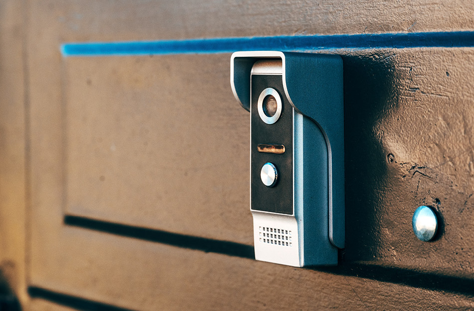
Remember that “security screw” mentioned at the beginning? The one that secures the device to the housing case? The case conveniently hides the SD card slot and the Power On/Off button, which is nice, but at the end of the day it is a single Torx screw. In case you are wondering, it will buy you about 15 seconds of security, as that’s how long it’d take to unscrew it and lift the device. Something to think about when saving footage and pictures to the SD card, which was completely unencrypted.


Figure 22: The device is secured in the housing case by a single Torx screw
With the SD card successfully mounted, we copied everything we needed onto it for extraction and further analysis. We even found a way to get the firmware copied over from our root shell thanks to previous research by DrmnSamoLiu [16], which did not require any clips or connecting to the flash chip directly (we tried it later anyway).
[root@Meari:~]# ls -la /mnt/mmc01
drwxr-xr-x 4 root root 4096 Jan 1 1970 .
drwxr-xr-x 3 root root 0 Nov 7 07:11 ..
drwxr-xr-x 5 root root 4096 Jul 1 22:00 binaries
-rwxr-xr-x 1 root root 16777216 Jul 1 21:16 firmware.bin
-rwxr-xr-x 1 root root 698860 Jul 3 11:35 libc.so.0
-rwxr-xr-x 1 root root 84400 Jul 3 11:20 libpthread.so.0
-rwxr-xr-x 1 root root 27 Jan 1 1980 readonly.bin
-rwxr-xr-x 1 root root 1572864 Jul 1 21:51 rootfs-mtdblock4.bin
-rwxr-xr-x 1 root root 1572864 Jul 1 21:49 rootfs.bin
drwxr-xr-x 3 root root 4096 Jul 1 22:05 sdrec
-rwxr-xr-x 1 root root 8388608 Jul 1 21:50 zram0.bin
-rwxr-xr-x 1 root root 0 Jul 1 21:50 zram1.bin
Figure 23: Files successfully copied from the device over to the SD card, including the entire firmware
So now we had access to the binaries and could work on reverse engineering them, to look for any vulnerabilities that could be exploitable. However, as we had ordered some kit for firmware extraction directly off the SPI flash chip, we also wanted to try this method.
There are two ways to go about dumping flash chip memory: a chip-on and a chip-off extraction method. The first, as the name suggests, is doing it with the chip still attached to the hardware, while the second requires de-soldering of the chip and then reading the contents. The second method is more destructive, so we left it as a backup option in case the first did not work. Why would the first method not work? Well there are pros and cons to both, but essentially there are some cases where reading the memory will not work while the chip is attached to the rest of the hardware, due to potential interference caused by data being read/written, and other signals being sent to the chip when power is applied to it, which can result in the read data being corrupted.
We already had the datasheet for the flash memory handy from our initial exploration of the hardware components on the board (the process is simple - read part number if present, search online for datasheets). So, we labelled the chip pinout for our convenience and reference and got to work.

Figure 24: SPI Flash chip pinout as determined from the datasheet
There is a very handy utility program named flashrom [17], which can be used to read and write data to a whole range of flash memory chips. For the programmer, we decided to use a CH341a programmer board that is compatible with flashrom.


Figure 25: CH341a programmer used for reading the SPI flash chip
We hooked everything up and were ready to try reading the contents of the flash chip – it took a few attempts as the SOP8 clip can be difficult to position correctly so that all pins make a good connection with the chip, (depends on the space available and the quality of the clip) but we got there in the end.

Figure 26: CH341a programmer connected to the SPI flash chip on the device
To check if the reader is detecting the chip, you can run the flashrom command specifying the programmer board type, if all is connected well and the chip is detected and recognised, you should see something similar to the below output:
$ flashrom -p ch341a_spi
flashrom v1.3.0 on Linux 6.9.3-arch1-1 (x86_64)
flashrom is free software, get the source code at https://flashrom.org
Using clock_gettime for delay loops (clk_id: 1, resolution: 1ns).
Found XMC flash chip "XM25QH64C" (8192 kB, SPI) on ch341a_spi.
===
This flash part has status UNTESTED for operations: PROBE READ ERASE WRITE WP
The test status of this chip may have been updated in the latest development
version of flashrom. If you are running the latest development version,
please email a report to flashrom@flashrom.org if any of the above operations
work correctly for you with this flash chip. Please include the flashrom log
file for all operations you tested (see the man page for details), and mention
which mainboard or programmer you tested in the subject line.
Thanks for your help!
No operations were specified.
Figure 27: SPI flash chip was detected and recognised by flashrom
We then went ahead and dumped the flash memory three times. Why three times? Because occasionally, depending on various factors, there may be read errors (cables too long, bad connection, other electronic components on the board causing interference when the chip is powered on, etc.), so we wanted to make sure nothing was corrupted.
$ flashrom -p ch341a_spi -r SDB_XTU_J7_SPI_Flash.bin
flashrom v1.3.0 on Linux 6.9.3-arch1-1 (x86_64)
flashrom is free software, get the source code at https://flashrom.org
Using clock_gettime for delay loops (clk_id: 1, resolution: 1ns).
Found XMC flash chip "XM25QH64C" (8192 kB, SPI) on ch341a_spi.
===
<SNIP>
Reading flash... done.
Figure 28: Firmware successfully dumped from the flash memory
All that is left at this point is to check the hashes of the flash dumps, and hopefully they should all be the same. If they are not, it means something went wrong with the read and some data was corrupted, so best to try again.
$ sha256sum SDB_XTU_J7_SPI_Flash*
9ecc31196f66b442ffa0e1737aada6109abf107e4557393877a9a525b093fa49 SDB_XTU_J7_SPI_Flash-read1.bin
9ecc31196f66b442ffa0e1737aada6109abf107e4557393877a9a525b093fa49 SDB_XTU_J7_SPI_Flash-read2.bin
9ecc31196f66b442ffa0e1737aada6109abf107e4557393877a9a525b093fa49 SDB_XTU_J7_SPI_Flash-read3.bin
Figure 29: Checking the SHA256 hash of each firmware dump to ensure no data was corrupted
So, let’s see what we have inside this firmware dump. A quick check to do would be running binwalk against the firmware dump. It may not always work, especially if the firmware is encrypted or compressed with some custom compression algorithm, however we got some promising results back. Running the tool without any options will simply analyse the file and return what binwalk thinks the file contains at various offsets, a sample of the output is shown below.
$ binwalk SDB_XTU_J7_SPI_Flash-read1.bin
DECIMAL HEXADECIMAL DESCRIPTION
--------------------------------------------------------------------------------
<SNIP>
198796 0x3088C Android bootimg, kernel size: 0 bytes, kernel addr: 0x70657250, ramdisk size: 543519329 bytes, ramdisk addr: 0x6E72656B, product name: "mem boot start"
688128 0xA8000 uImage header, header size: 64 bytes, header CRC: 0x60F5B871, created: 2024-01-09 03:31:18, image size: 2564320 bytes, Data Address: 0x80010000, Entry Point: 0x803DE030, data CRC: 0xBFA70C44, OS: Linux, CPU: MIPS, image type: OS Kernel Image, image name: "Linux-3.10.14-Archon"
<SNIP>
4037120 0x3D9A00 SHA256 hash constants, little endian
<SNIP>
4768500 0x48C2F4 Certificate in DER format (x509 v3), header length: 4, sequence length: 831
<SNIP>
4882432 0x4A8000 Squashfs filesystem, little endian, version 4.0, compression:xz, size: 1895238 bytes, 51 inodes, blocksize: 131072 bytes, created: 2024-01-25 01:37:27
7864320 0x780000 JFFS2 filesystem, little endian
Figure 30: Sample of binwalk output after analysing the firmware dump file
To get binwalk to extract various sections from the file, you can specify the -e option, which normally works well on known file types, and it supports quite a few although some may need installing additional tools (e.g. for extracting SquashFS or JFFS2 filesystems). Once we got all the dependencies installed, we managed to extract and unpack the SquashFS and JFFS2 filesystems from the dump which contained some of the files we’ve obtained from the device already. We could not get the root filesystem though, and that could be due to different compression algorithm used (one not recognised by binwalk) or some other custom activities applied to the image contained within the firmware. However, since we got everything we needed from the device via our UART shell, it was not much of a problem - something to potentially investigate later if time allows. If we could not get a UART shell, then we would probably need to spend a little more time extracting everything from the firmware dump.
Wrap up
We are almost at the end of this article that covered our initial exploration of an IoT Smart Doorbell device. We successfully managed to complete the first three phases of the research path we have chosen, which gave us interactive access to the device and helped with mapping out a potential attack surface. We have made a start on the next phase as well, which is vulnerability research, however we have not really covered it here as there is still a lot of work ahead.
So, what are the different potential attack paths then? Well, there are a few and each is a little different in terms of how it can be approached, but we have determined these may be the possible areas for further research and potentially attacking the device:
Network services
The device has several UDP ports opened by the main process and listening on the local network, so a typical vector on that could include finding bugs in the main process binary and trying to exploit it over the network. This could include things like buffer overflows, logic bugs, etc. to achieve command execution on the device. Of course, that would need the attacker to be present on the local network, or somehow be able to route traffic to the device, so the scenario here is an adversary in such a position.
Cloud services and mobile app
The mobile app and the cloud server provide the ability to communicate with the device over the internet, so it is a potential path to take control over the device remotely without the need to be on the same local network. This would require some bugs or security vulnerabilities in the way authentication and authorisation are performed, and possibly some information disclosure which could allow establishing communication with an arbitrary device. We have seen some requests and their parameters when observing the network traffic from the mobile app, and from the debug output on the device, with some values likely to be the device identifiers (e.g. a serial number which is also the hostname). In such instances, bugs like IDORs (Insecure Direct Object Reference) could be a viable way to achieve this. Although the requests appeared to be signed with a cryptographic key, that key is residing somewhere on the device or possibly within the mobile app itself (and what if it’s the same for each device? It would not be the first instance of hardcoded credentials [18]).
Physical
There is also the physical attack vector that could be considered - although not really the focus in our research. The housing case of the device is screwed into a wall with two screws and some Rawl plugs (dependent on the surface), and the device itself is secured to the casing with a single Torx screw. If someone decided to steal such a device, it would not be much of a challenge and does not require advanced tooling. Given the SD card storage is not encrypted, and the home Wi-Fi password is stored somewhere on the device, it’s something worth considering. However, that does require an attacker to know where you live and come over for a visit. Nonetheless, something to keep in mind, especially if such devices are used within corporate environments where a Wi-Fi password could be an entry point for further compromise (it is a good idea to segregate your corporate and IoT networks).
Next Steps
For the purposes of this project, we would focus on the first two areas (e.g. network services and mobile/cloud) to find ways of attacking the device. It will involve some reverse engineering and code analysis to find bugs that could be exploitable, and this is what phase four would be focusing on.
Before we part, let’s review the main binaries we pulled off the device, and see what we’re dealing with in terms of protections. Below is the output from the file and checksec commands which show what file type is detected, and the security mechanisms enabled on the binary.
$ file usr/bin/ppsapp
usr/bin/ppsapp: ELF 32-bit LSB executable, MIPS, MIPS32 rel2 version 1 (SYSV), dynamically linked, interpreter /lib/ld-uClibc.so.0, stripped
$ checksec --file=usr/bin/ppsapp --output=json | jq
{
"usr/bin/ppsapp": {
"relro": "no",
"canary": "no",
"nx": "no",
"pie": "no",
"rpath": "no",
"runpath": "no",
"symbols": "no",
"fortify_source": "no",
"fortified": "0",
"fortify-able": "18"
}
}
Figure 31: Output of file and checksec commands for the main process binary from the doorbell
It turned out these binaries were compiled without any protections against attacks like buffer overflows, stack smashing, GOT overwrites, etc. What does this mean for us? Well, if there are bugs in the binary that could lead to buffer overflows, provided they were exploitable, it would be relatively easy to exploit them without having to bypass any mitigations (we’re back to the 90s here in terms of binary protections). This should be an interesting exploration when we get to it, which we plan to cover in future articles.
Summary
In this article we covered an initial exploration of the XTU Smart Doorbell with a camera – a COTS (commercial off-the-shelf) white label device. It covered our approach to the project planning, background research, target selection, a little bit of threat modelling and then a few aspects of the practical evaluation, including obtaining interactive access to the device and harvesting data for further research.
Over the years, IoT devices have made the news headlines many times, and continue to do so even today. Some of the more serious issues included data breaches, compromised devices, massive botnets, or serious vulnerabilities which can put your data and privacy at risk. We considered several things when it comes to using such devices at homes and in commercial settings, and here are some of the main points that are worth considering, before you decide to deploy an IoT device in your home or organisation:
- Using devices from unfamiliar brands may pose risks, especially if the update processes and support systems are unclear or unestablished. This can be further complicated with white-label products, where it is often unclear who should be notified about security vulnerabilities or responsible for issuing fixes.
- A network's security may only be as strong as its least secure device. When evaluating IoT devices, consider the potential impact of a device compromise. To protect critical systems and sensitive data, it is good practice to isolate untrusted or potentially vulnerable IoT devices on a separate network. While this level of segmentation may be hard for everyday users on a home network, investing in a reputable brand can help reduce the risks when connecting these devices.
- Physical security and access are a legitimate concern. Depending on what data is stored and how it is protected on the device, physical security and access restrictions may be more or less important. However, consider what data your devices may store, who has access to these devices, and what could happen if someone gained unauthorised physical access to one of these devices.
Get in touch
Do you use IoT devices on your network? And if so, do you know if they are segregated from other sensitive systems? Do you have a process to patch these devices, and support from the vendor for addressing security issues? Do you know what data is stored on these devices, where it is sent, and how it is secured on the device itself? What would happen is one of these devices went missing?
These are just a few of the questions you should be asking yourself if you have IoT devices on your organisation’s network. If you are interested in an evaluation of the security posture of your IoT devices and infrastructure, contact us and we can discuss your organisation’s setup. Our solutions can give you an insight into the current state of your infrastructure and devices, the associated risks and recommendations for improving your resilience, ensuring risk from IoT devices is minimised to protect your organisation’s data.
References
[1] - https://www.ibm.com/think/topics/eot-for-telecommunications
[2] - https://explodingtopics.com/blog/number-of-iot-devices
[3] - https://www.pcmag.com/picks/the-best-smart-home-devices
[4] - https://www.techtarget.com/iotagenda/definition/Industrial-Internet-of-Things-IIoT
[5] - https://www.cloudflare.com/learning/ddos/glossary/mirai-botnet/
[6] - https://thehackernews.com/2024/08/unpatched-avtech-ip-camera-flaw.html
[7] - https://thehackernews.com/2024/09/beware-new-vo1d-malware-infects-13.html
[8] - https://www.theregister.com/2024/03/09/opinion_column_security_sjvn/
[10] - https://fcc.report/FCC-ID/2AUSP-BELLJ6
[11] - https://www.circuitbasics.com/basics-uart-communication/
[12] - https://github.com/OWASP/owasp-istg/tree/main
[14] - https://threatpost.com/hacker-leaks-more-than-500k-telnet-credentials-for-iot-devices/152015/
[16] - https://drmnsamoliu.github.io/firmware.html
[17] - https://www.flashrom.org/


